產品資訊 - 照明
Applied image ISO12233:2023 Edge SFR Chart
Applied image ISO12233:2023 Edge SFR Chart
This test pattern is an image evaluation tool for determination of resolving power,
limiting resolution and spatial frequency response (SFR) of digital image systems at a
low contrast signal point.
Image Description:
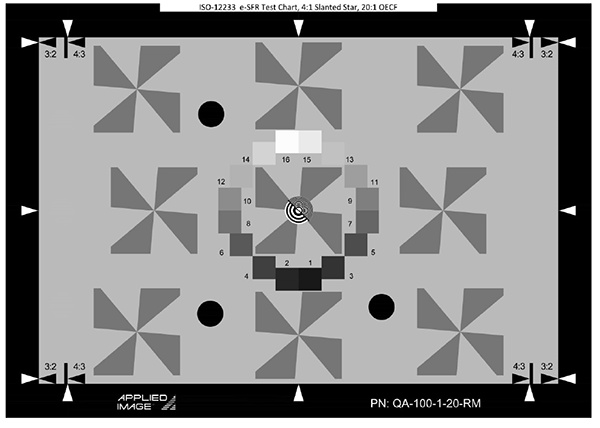
The ISO-12233:2023 Low Contrast Edge SFR chart with OECF Patches contains
a new version of the slant edge test pattern, users are advised to refer to International
Standard ISO-12233:2023 for a detailed explanation of the target’s features and their
use. The following is a summary list of image features.
1X size, 340 x 240 mm size, photographic material
Framing arrows which define 4:3 and 3:2 aspect ratios assist in framing the
target's active area.
A central multi-frequency zone plate can be used to set focus.
Four-cycle slanted star test patterns with 4:1 edge reflectance ratio provide Edge
SFR (e-SFR) at multiple locations.
Spectrally neutral gray scale patches with 20:1 luminance ratio used to
determine the optoelectronic conversion functions (OECFs) described in ISO
14524
Polarity: Positive image features
Image Contrast: The background reflectance varies with the particular chart used. See
ISO 12233:2023 for values.
Terms:
Aliasing – The appearance of image artifacts due to limited or diminished
resolution.
Aliasing ratio – The quantity of image distortion due to aliasing expressed as the
ratio of maximum minus minimum response to the average response within a burst
pattern (a series of line and space features at a slight angle to the image sensor).
Image aspect ratio – The ratio of image width to image height.
Resolution – The measure of a camera or imaging component to convey detail.
SFR (Spatial Frequency Response) – The amplitude response of an imaging system
as a function of relative spatial frequency.
Spectrally neutral – Spectral power distributions of equal value.
Guidelines for Usage:
This document is not intended to replace the International Standard Document
ISO-12233:2023. However, the following guidelines will aid the first use of this chart.
The chart should be illuminated uniformly (±10% of center luminance) against a
surround of low reflectance and with a minimum of flare light. The illuminant
should be effectively neutral with respect to either daylight or tungsten illuminants
(ISO-7589). Camera white balance should be adjusted to provide equal red, green
and blue signal levels.
The camera should be positioned to provide centered, full-frame-height rendering of
the chart’s active area. Use the chart’s framing arrows and horizontal edges to aid
positioning. The camera to test chart distance should be noted.
Use the chart’s central zone plate feature to set good focus.
Set camera lens aperture and exposure time to provide maximum signal from white
areas while avoiding any signal clipping.
Where possible, image compression features should be disabled.
Camera output signal should be linearized using the standard reflection camera
OECF (Opto-Electronic Conversion Function) test chart, Applied Image part
number ST-52-RM, or the test patches provided on this chart.
Back